I wanted to make something to keep my Raspberry PI 3B+ handy and accessible on my office desk. Something retro and infinitely configurable. What about a hands-on, mechanical switch computer and breakout board desktop toy!
Here was the idea, sketched out during a work meeting, starting with the components of the relay computer.

The base components

First photoshop concept sketch to play with component layout options. All the switches and LEDs on the left would be a fun fidget area to demonstrate boolean logic, the core of the modern computer. Again, I'm going to build all the "gates" with relays.

With the mini touchscreen and case


Starting the relay computer

This relay has five connections as shown in the picture below.

An electronic relay is an electric switch that uses power and an electromagnet to close a connection. This mirrors the behavior  of a semiconductor transistor - the core element of all modern computers. I decided to make a rudimentary "Relay Computer" which uses no semiconductors and visually displays the state of each switch "bit" with an LED.
Since computers use binary data, signals are very simple: 0 (no voltage) or 1 (voltage). I'm going to use 5V relays because the simple 1-volt voltage is too low to have large amperage's and not too high to have problems with dissipating the power for the used LED’s.
A combination of several relays can realize almost every function that can be found in a relay computer. However, in a number of cases, it is more efficient to use one or more diodes. Since (flyback) diodes are also necessary to protect the LED’s that connected parallel to the relay and diodes play an important role in the memory implementation, I choose to incorporate diodes into the designs.
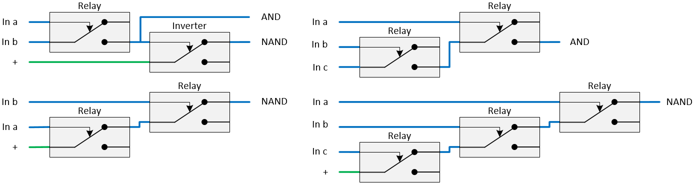
AND and NAND gates - the bricks of the computer
The output of an AND gate will only give 1 when both inputs are 1. For a two input port, only one relay is needed. For every extra input one extra relay is needed. Another relay is used to invert the signal.
OR and NOR gates
Just connecting the lines together, can create an OR gate. However, if an input becomes 1, all the other inputs – even if they are 0 - will also become 1. This can create unwanted feedback to relay’s earlier in the switching chain. This problem is eliminated by adding diodes, as shown with the red lines in the picture below. Then the signal cannot be fed back to the other inputs. For a NOR port, an inverting relay is added.

Raspberry Pi 3 Notes
(Until I make a section)
How to find IP Address on a Raspberry Pi 3
First, open the terminal on your Pi (black icon in the top toolbar), then type in the command:
ifconfig
Make the Raspberry Pi 3 a mapped network drive on Windows 10
https://www.youtube.com/watch?v=4P5nEH9zGDI
How to Mount a USB2 harddrive to your Raspberry Pi 3
https://pcmac.biz/raspberry-pi-mount-usb-drive.html